
Ever wondered why your power meters sometimes show wrong readings or why protection relays don’t work as expected? The answer often lies in the current transformer polarity (CT polarity). Don’t worry—we’ll break this down into simple, easy-to-understand concepts.
What is Current Transformer Polarity? (The Basics)
Think of current transformer polarity like the direction of water flow in a pipe. Just as water flows from high pressure to low pressure, electrical current flows in a specific direction. In a current transformer (CT), we need to know which way the current is flowing to get accurate measurements.
Simple Definition: Current transformer polarity tells us about the relationship between current direction in the primary (high voltage) side and secondary (measurement) side of the transformer.
Why Does Polarity Matter?
Imagine you’re measuring water flow with two meters—one at the inlet and one at the outlet. If you connect them backwards, you’ll get wrong readings. The same thing happens with current transformers:
- Correct polarity = Accurate power measurements
- Wrong polarity = Incorrect readings and potential equipment damage
Two Types of CT Polarity (Keep It Simple)
1. Subtractive Polarity (Most Common)
- What it means: When current enters H1 terminal, it exits X1 terminal at the same time
- Memory trick: H1 and X1 are “”buddies”—they have the same polarity
- Where you’ll find it: Almost all modern electrical installations
- Perfect for power system protection
2. Additive Polarity (Less Common)
- What it means: When current enters H1 terminal, it exits X2 terminal
- Memory trick: H1 pairs with X2 (opposite terminals)
- Where you’ll find it: Older installations or special applications
- Requires extra care during CT installation
How to Test CT Polarity (Simple Methods)
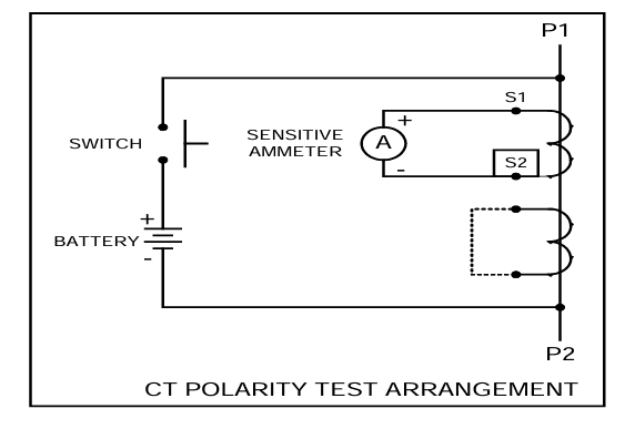
Method 1: The Battery Test (Most Popular)
What You Need:
- One 9-volt battery (like from a smoke detector)
- A simple needle meter (galvanometer)
- A push-button switch
- Some wire
Step-by-Step Process:
- Connect the battery to the CT primary (big terminals) through the switch
- Connect the meter to the CT secondary (small terminals)
- Press the button quickly and watch the needle
- Read the result:
- Needle moves right (positive) = Subtractive polarity ✓
- Needle moves left (negative) = Additive polarity
Why This Works: When you connect the battery, it creates a magnetic field. When you disconnect it, the field collapses and creates a current pulse. The direction of this pulse tells us the polarity.
This simple test is widely used in substation testing because anyone can do it safely.
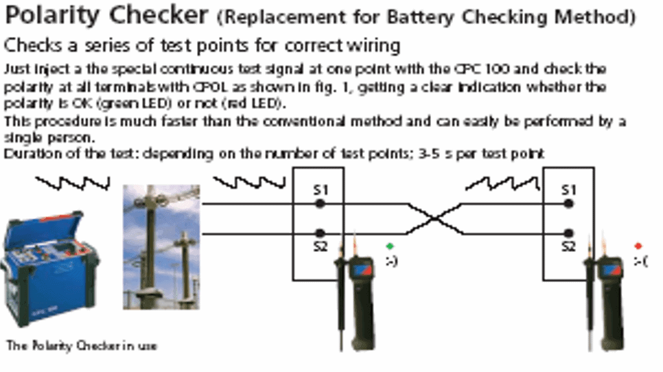
Method 2: Modern Test Equipment (CPC 100)
Advantages of Digital Testing:
- No guesswork—the digital display shows clear results
- Automatic testing—just connect and press start
- Data recording – saves results for your records
- Professional reports—great for substation commissioning
How It Works:
- Connect test leads to CT terminals
- Follow the equipment menu
- Read the digital result
- Save to maintenance records
Advanced Testing (For Professionals)
If you’re doing detailed testing, here’s a more comprehensive approach:
Professional Test Steps
Before You Start:
- Make sure the CT is not energized (safety first!)
- Check your test equipment
- Review safety procedures
The Testing Process:
- Wire Connection: Connect matching terminals together (1 to 1)
- Meter Setup: Connect DC voltmeter to high-voltage winding
- Battery Connection: Connect battery for positive reading
- Switch Meter: Move meter to low-voltage side
- Watch the Kick: Disconnect battery and observe meter movement
Reading Results:
- Meter kicks down = Same polarity (subtractive)
- Meter kicks up = Opposite polarity (additive)
How Polarity Affects Power Flow Direction
Here’s where it gets really practical. Understanding current transformer polarity direction helps you know whether power is coming in (import) or going out (export).
Power Import Scenario
What Happens:
- Current flows toward the star point (neutral connection)
- CT secondary shows current going to S1, S2, S3 terminals
- Your energy meter reads positive (importing power)
- Real-world example: Your facility is using power from the grid
Power Export Scenario
What Happens:
- Current flows away from star point
- CT secondary shows current leaving the terminals
- Your energy meter reads negative (exporting power)
- Real-world example: Your solar panels are sending power back to the grid
This is crucial for accurate energy metering in today’s bidirectional power systems.
Identifying CT Polarity Markings (Visual Guide)
What to Look For
On the Primary Side (High Voltage):
- H1 and H2 terminals (clearly marked)
- Polarity dot (usually white or colored dot on H1)
- Arrow symbols showing current direction
On the Secondary Side (Low Voltage):
- X1 and X2 terminals (smaller terminals)
- Matching polarity marks
- Star point connections (for three-phase systems)
Quick Visual Tips
- Check the nameplate for CT polarity markings
- Look for dots, arrows, or + symbols
- Verify terminal numbers match drawings
- Cross-reference with substation layouts
Safety First: Testing Precautions
Before Testing (Critical Steps)
- Turn off all power—verify with proper test equipment
- Use safety equipment—proper PPE equipment
- Have emergency plan ready
- Get authorization before starting work
During Testing (Stay Safe)
- Battery on high side only—reduces dangerous voltage kicks
- Use insulated tools and hot sticks
- Wear rubber gloves for all connections
- Keep safe distance from energized parts
After Testing (Don’t Forget)
- Demagnetize the CT using AC source
- Record all results properly
- Secure all connections before leaving
- Update maintenance logs
Watch Out For These Dangers
High Voltage Kicks:
- Can reach thousands of volts instantly
- May damage equipment or injure personnel
- Always disconnect quickly and safely
Arc Flash:
- Occurs when disconnecting battery
- Use proper switching equipment
- Keep fire suppression equipment nearby
Real-World Applications
Protection Systems
Correct current transformer polarity ensures:
- Fault detection works properly
- Overcurrent protection operates correctly
- Backup systems coordinate properly
- Relay settings perform as designed
Revenue Metering
Why Accuracy Matters:
- Billing accuracy—no one wants to pay wrong amounts
- Import/export tracking—especially important for solar installations
- Demand response programs – utilities need accurate data
- Net metering—critical for renewable energy credits
Troubleshooting Common Problems
Problem 1: Negative Power Readings
What You See: Energy meter shows negative values when it should be positive
Quick Fixes:
- Check CT orientation (might be backwards)
- Verify polarity connections
- Review metering circuits for errors
Problem 2: Protection Relay Issues
What You See: Relays trip when they shouldn’t or don’t trip when they should
Quick Fixes:
- Check directional relay settings
- Verify CT polarity connections
- Review protection schemes coordination
Problem 3: Energy Meter Confusion
What You See: Import/export readings don’t match actual power flow
Quick Fixes:
- Verify CT installation direction
- Check star point connections
- Update meter programming if needed
Easy Field Corrections
If you find polarity problems, here are simple fixes:
Method 1: Swap Secondary Wires
- Switch X1 and X2 connections
- Easiest fix for most situations
- Document the change properly
Method 2: Update Relay Settings
- Change polarity settings in digital relays
- Modify protection logic as needed
- Record all configuration changes
Best Practices (Keep It Simple)
Installation Tips
- Use consistent standards across your facility
- Document everything with photos and diagrams
- Train your team on proper procedures
- Follow quality control checklists
Testing Documentation
- Record all test results in detail
- Take photos of connections before and after
- Update drawings to match actual installation
- Keep technical specifications current
Maintenance Schedule
- Test polarity during annual maintenance
- Check connections for tightness
- Verify insulation resistance values
- Demagnetize cores after DC testing
Key Takeaways
Understanding current transformer polarity doesn’t have to be complicated:
- Polarity determines accuracy—get it right for correct measurements
- Two main types exist—subtractive (common) and additive (rare)
- A simple battery test works for basic verification
- Safety is critical—always de-energize before testing
- Documentation matters—record everything for future reference
Regular current transformer polarity tests should be part of your maintenance program. When in doubt, test it out—a few minutes of testing can prevent costly mistakes and dangerous situations.
Need More Help?
For detailed guides on power system protection and testing procedures, visit substationfaults.com—your complete resource for electrical substation information.