
Transformer testing is checking the transformer’s condition using different tests. These tests find problems before they cause breakdowns. Think of it like getting a health check-up for your transformer.
Transformer Testing Standards
Transformer testing standards are rules that tell us how to test properly. Major standards include:
- IEEE C57 Series – American standards for transformer testing
- IEC 60076 Series – International standards used worldwide
- ASTM Standards – For oil testing
- NETA Standards – For field testing procedures
These transformer testing standards make sure everyone tests the same way and gets reliable results.
How Many Types of Transformer Testing Are There?
There are three main types of transformer testing:
1. Routine Tests
Done on every new transformer at the factory:
- Insulation resistance
- Winding resistance
- Voltage ratio
- No-load test
- Load loss test
2. Type Tests
Done on sample transformers to check the design:
- Temperature rise test
- Lightning impulse test
- Short circuit test
- Noise level test
3. Special Tests
Done when customer requests or for special cases:
- Zero sequence impedance
- Harmonic tests
- Acoustic tests
In the field, we do 12 common transformer testing types to check if the transformer is healthy. Let’s look at each one.
Transformer Testing Equipment List
Before testing, you need the right tools. Here’s a complete transformer testing equipment list:
Main Testing Equipment:
- Insulation Tester (Megger) – Tests insulation strength (5kV and 10kV)
- Micro-Ohmmeter – Measures very small resistances
- TTR Test Set – Checks turns ratio
- Doble Test Set – Measures power factor and tan delta
- FRA Analyzer – Finds mechanical damage
- Oil BDV Tester – Tests oil strength
- Power Source – For energizing tests
- Clamp Meters – Measures current without breaking circuits
Support Equipment:
- Temperature sensors
- Oil sampling bottles
- Cleaning materials
- Safety grounding cables
- Test leads and connectors
- Test forms for recording data
Important: All transformer testing equipment must be calibrated regularly. Non-calibrated equipment gives wrong results.
12 Essential Transformer Testing Procedures
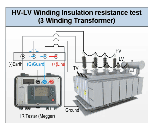
Test 1: Insulation Resistance Test
What it does: Checks if insulation is good or damaged
Equipment needed: Insulation resistance tester (Megger) – 5kV
How to do it:
- Clean all bushings thoroughly
- Connect tester between windings or winding to ground
- Apply 5kV for 10 minutes
- Record readings at 1 minute and 10 minutes
Tests to perform:
- HV to LV winding
- HV to TV winding
- LV to TV winding
- Each winding to ground
Calculation: Polarization Index (PI) = 10 min reading ÷ 1 min reading
Pass criteria: PI must be 1.25 or higher
What results mean:
- High PI (above 2.0) = Good insulation
- Low PI (below 1.25) = Moisture or damaged insulation
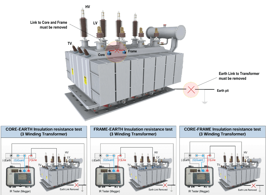
Test 2: Core and Frame Insulation Test
What it does: Checks insulation between core, frame, and ground
Equipment needed: Insulation tester – 1kV
How to do it:
- Clean bushings
- Apply 1kV between core and earth
- Apply 1kV between frame and earth
- Apply 1kV between core and frame
- Measure for 1 minute
Pass criteria: Reading must be above 10 MΩ (mega-ohms)
What results mean:
- Above 10 MΩ = Good
- Below 10 MΩ = Problem with insulation
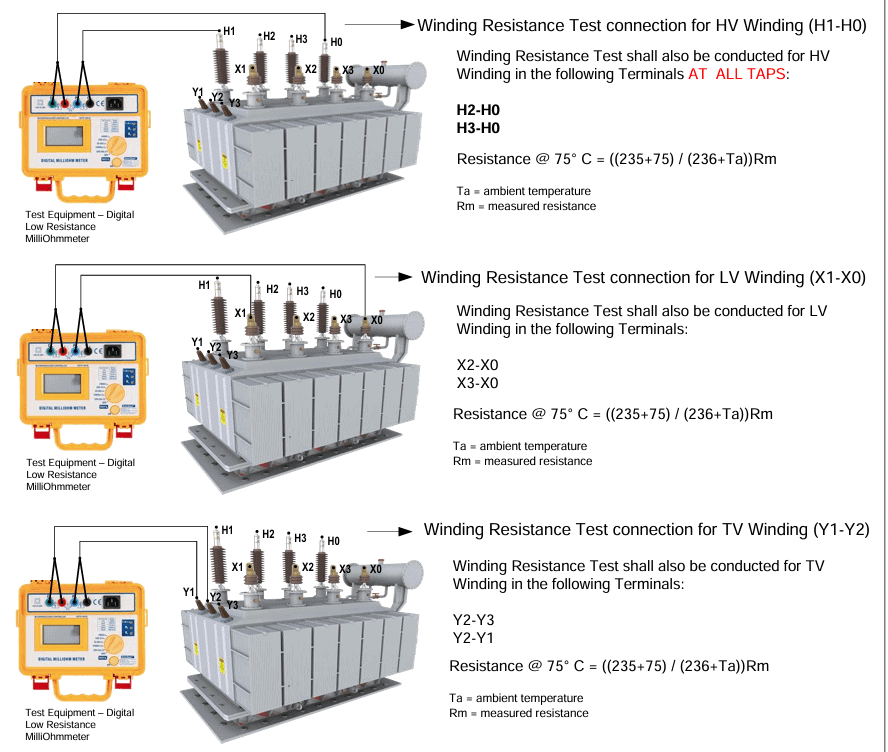
Test 3: Winding Resistance Test
What it does: Finds loose connections or broken wires inside
Equipment needed: Digital micro-ohmmeter
How to do it:
- Connect meter to winding terminals
- Measure resistance of HV winding at all taps
- Measure resistance of LV winding at all taps
- Measure resistance of TV winding at all taps
- Correct readings for temperature
Temperature correction formula: Resistance @ 75°C = [(235 + 75) ÷ (235 + Ta)] × Measured resistance
Where Ta = temperature during test
What results mean:
- Compare with previous test results
- Big change (more than 5%) = Problem
- All three phases should be similar
Test 4: No-Load Test (Excitation Test)
What it does: Measures current when transformer is energized but not loaded
Equipment needed: Power source, clamp meter
How to do it:
- Apply rated voltage to one winding
- Keep other windings open
- Measure no-load current
- Test at first tap, middle tap, and last tap
What results mean:
- Compare with nameplate values
- High current = Core problem or short circuit
- Should be less than 2% of rated current
Test 5: Short Circuit Test (Impedance %Z Test)
What it does: Measures transformer impedance
Equipment needed: Power source, voltmeter, ammeter
How to do it:
- Short circuit one winding
- Apply low voltage to other winding
- Measure voltage and current
- Test at all tap positions
Calculation: %Z = (Measured Voltage ÷ Rated Voltage) × 100
What results mean:
- Must match nameplate %Z (±10% tolerance)
- Wrong %Z = Winding damage or tap changer problem
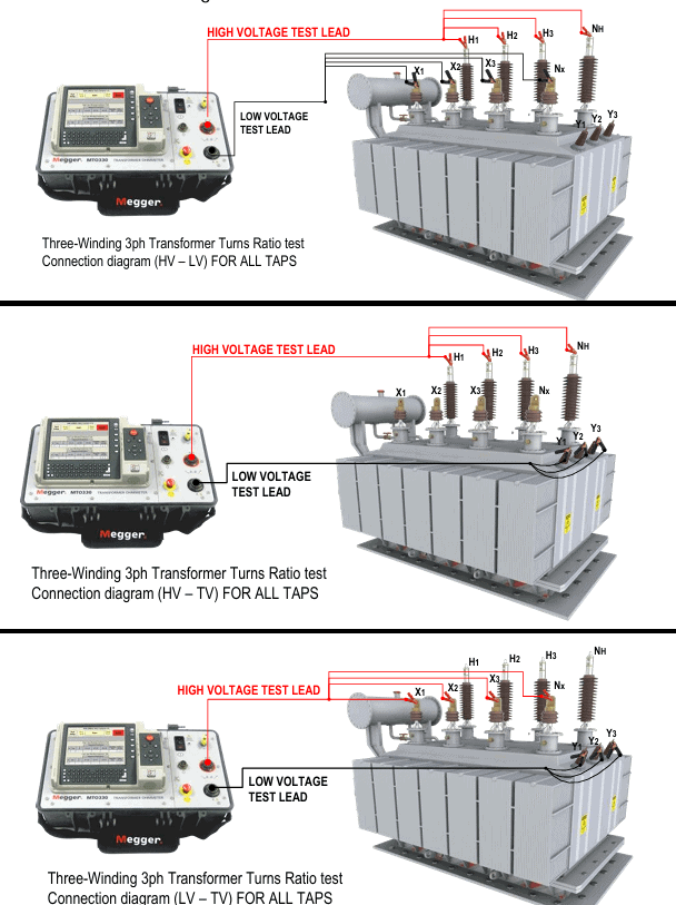
Test 6: Turns Ratio Test (TTR Test)
What it does: Checks if voltage ratio is correct
Equipment needed: TTR test set
How to do it:
- Connect TTR to transformer
- Test HV to LV ratio at all taps
- Test HV to TV ratio at all taps
- Test LV to TV ratio at all taps
What results mean:
- Must match calculated ratio (±0.5% tolerance)
- Wrong ratio = Shorted turns or tap changer problem
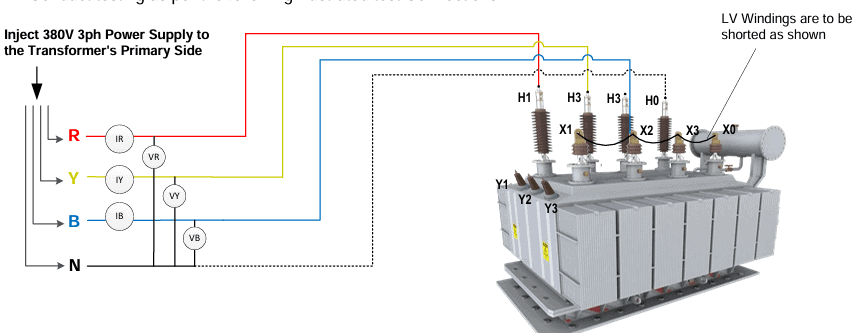
Test 7: Magnetic Balance Test
What it does: Checks if core is magnetically balanced
Equipment needed: 230V single-phase power source, voltmeter
How to do it:
- Inject 230V across two phases (R-N)
- Measure voltage on other phases
- Repeat for Y-N phases
- Repeat for B-N phases
Pass criteria: Injected voltage = Sum of other phase voltages
What results mean:
- Balanced = Good core
- Not balanced = Core problem
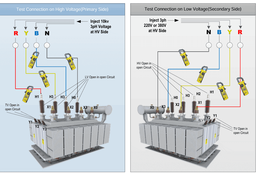
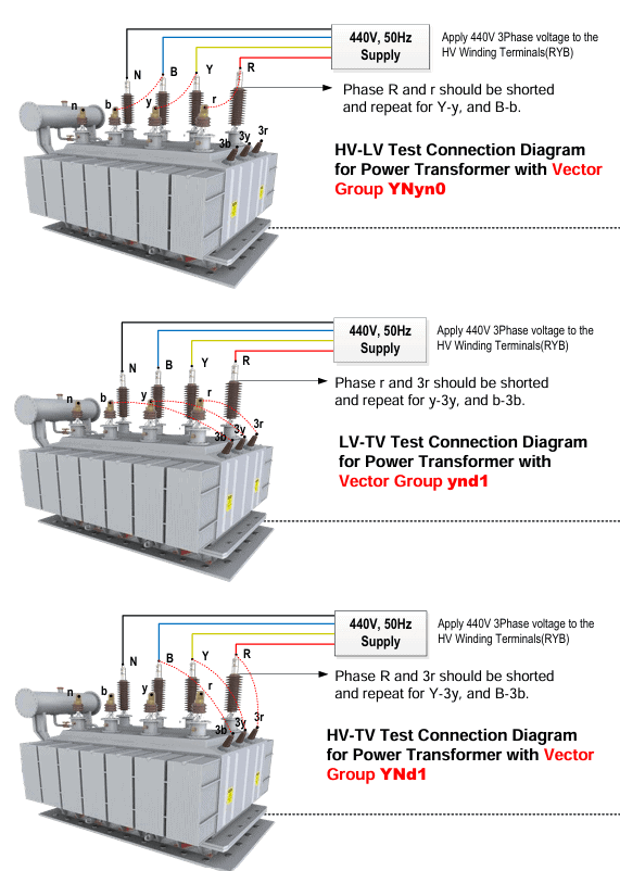
Test 8: Vector Group Test
What it does: Checks phase relationship between windings
Equipment needed: Power source, voltmeter
How to do it:
- Keep tap changer at normal position
- Apply single-phase voltage to HV
- Measure voltages on all terminals
- Check phase angles
What results mean:
- Must match nameplate vector group
- Wrong vector = Incorrect connections
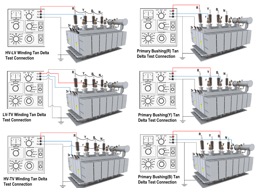
Test 9: Tan Delta Test (Power Factor Test)
What it does: Finds insulation problems very accurately
Equipment needed: Doble test set or equivalent
How to do it:
- Short and ground all windings except test winding
- Apply 10kV test voltage
- Equipment automatically measures power factor
- Test each winding separately
What results mean:
- Low tan delta (below 0.5%) = Good insulation
- High tan delta (above 1%) = Moisture or aging
- Increasing trend = Insulation getting worse
Test 10: Zero Sequence Impedance Test
What it does: Measures impedance for ground faults
Equipment needed: Power source, voltmeter, ammeter
How to do it:
- Short LV winding, open TV winding
- Apply voltage to HV winding (all three phases together)
- Measure voltage and current
- Repeat with different winding combinations
Calculation: Z% = [3 × (Measured V ÷ Measured I) × (Rated V ÷ √3)] ÷ Rated Current
What results mean:
- Used for ground fault protection settings
- Must match manufacturer data
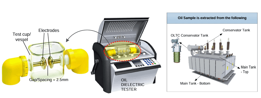
Test 11: Oil Dielectric Breakdown Test (BDV Test)
What it does: Tests if transformer oil is good
Equipment needed: Oil BDV tester, test cup
How to do it:
- Take oil sample from transformer
- Clean test cup with clean solvent
- Fill cup with oil to mark
- Let oil settle for 3-5 minutes
- Apply increasing voltage until breakdown
- Repeat test 6 times and take average
Pass criteria:
- For 60-230kV transformers: above 50kV
- For 380kV transformers: above 50kV
What results mean:
- Above 50kV = Good oil
- Below 50kV = Moisture, particles, or contamination – filter or replace oil
- Below 30kV = Dangerous – must replace oil immediately
Test 12: Frequency Response Analysis (FRA)
What it does: Finds mechanical damage or movement inside transformer
Equipment needed: FRA analyzer
How to do it:
- Connect analyzer to transformer terminals
- Test using four methods:
- End-to-end open circuit
- End-to-end short circuit
- Capacitive inter-winding
- Inductive inter-winding
- Save results as baseline or compare with previous results
What results mean:
- Compare with previous tests on same transformer
- Compare with sister transformers
- Compare between phases
- Big differences = Mechanical damage from short circuit or transport
Additional Transformer Testing Procedures
Temperature Sensor Testing
What it does: Makes sure temperature indicators work correctly
How to test oil temperature sensor:
- Heat oil in container
- Put sensor in hot oil
- Check if reading matches actual temperature
How to test winding temperature sensor:
- Inject current into heater circuit
- Wait 45 minutes
- Check temperature rise
Pass criteria: Must match transformer manual specifications
Cooling Fan Motor Test
What it does: Checks if cooling fans work properly
How to do it:
- Measure insulation resistance of motor
- Measure starting current (all 3 phases)
- Measure running current (all 3 phases)
- Remove one phase and test again
- Check if fans rotate in correct direction
What results mean:
- Compare with manufacturer data
- High current = Motor problem
- Wrong direction = Incorrect wiring
OLTC (On-Load Tap Changer) Motor Test
What it does: Tests tap changer motor operation
How to do it:
- Measure motor starting current
- Measure motor running current
- Test with one phase removed
- Measure voltages during operation
- Check rotation direction (should be clockwise)
- Measure contact resistance at all tap positions
What results mean:
- Compare with previous results
- High resistance = Contact wear
- Wrong direction = Will damage tap changer
Best Practices for Transformer Testing
Following proper transformer testing procedures ensures accurate results:
- Always use calibrated equipment – Wrong equipment = wrong results
- Clean bushings before testing – Dirt causes wrong readings
- Record ambient temperature – Affects test results
- Take photos – Document connections and conditions
- Compare with previous tests – Trends show problems early
- Follow safety rules – Use proper grounding and PPE
- Test before peak season – Find problems before high load
- Keep detailed records – History helps find developing problems
Understanding Test Results
Good transformer shows:
- Insulation resistance increasing with time (good PI)
- Winding resistance similar to previous tests
- No-load current matches nameplate
- Oil BDV above 50kV
- All ratios match calculations
Problem transformer shows:
- Decreasing insulation resistance
- Winding resistance changed more than 5%
- High no-load current
- Low oil BDV
- Wrong ratios or impedance
When to Perform Transformer Testing
Different transformer testing types have different schedules:
Annual Testing:
- Insulation resistance test
- Oil BDV test
- Temperature sensor check
Every 3-5 Years:
- Winding resistance test
- Turns ratio test
- Tan delta test
- Core insulation test
After Events:
- After short circuit – Do FRA test
- After transport – Do all tests
- After maintenance – Do relevant tests
- After fault – Do complete testing
Before Commissioning:
- Do all 12 tests
- Create baseline data for future comparison
Conclusion
Transformer testing is essential for reliable power systems. Understanding different transformer testing methods and following proper transformer testing procedures helps find problems early.
For more information on transformer maintenance and substation testing, visit Substation Faults.
Related Topics:
External Resources: