
What is an Anti Pumping Relay?
An anti pumping relay (also called antipumping relay or Y-relay and ANSI 94 Trip or Trip-Free Relay) is a protective device that prevents a circuit breaker from closing repeatedly when a continuous close command is present. In simple terms, it stops your circuit breaker from “pumping” – which means opening and closing rapidly in succession.
Think of it like this: if you hold down a close button continuously, without an this relay, the breaker would keep trying to close over and over again. This can seriously damage the circuit breaker mechanism and create dangerous electrical conditions in your substation.
Why Do We Need Anti Pumping Relay?
The Problem It Solves
Imagine this scenario: An operator or control system gives a close command to a circuit breaker, but at the same time, a protection relay detects a fault and sends a trip command. Without anti pumping protection, here’s what would happen:
- CB receives close command and closes
- Protection relay trips the CB due to fault
- CB receives another close command (because the signal is still there)
- CB closes again
- Protection trips it again
- This cycle repeats rapidly
This repeated operation is called “pumping” and it can:
- Damage the circuit breaker closing coil and operating mechanism
- Cause severe mechanical wear
- Create dangerous arc conditions
- Reduce equipment lifespan
- Cause system instability
The anti pumping relay prevents all of this by allowing only ONE close operation per close command.
How Does Anti Pumping Relay Work?
Let me explain the working principle in simple steps that any technician can understand:
Step-by-Step Operation
Step 1: Normal Close Command
- Operator presses the close button or switches TNC (Trip-Neutral-Close) switch to close position
- Close command energizes the closing coil
- Circuit breaker closes successfully
- ANSI 94 (Y-relay) gets energized
Step 2: Relay Seals Itself In
- Once energized, the anti pumping relay “seals in” (holds itself energized)
- This happens through auxiliary contacts
- Even if the close command remains, the relay stays picked up
Step 3: Opens the Close Circuit
- The sealed-in anti pumping relay opens a contact in the close circuit
- This electrically isolates the closing coil
- No further closing operations can occur
Step 4: Reset Condition
- The only resets when the close command is removed
- OR when the circuit breaker trips open
- After reset, the system is ready for the next close operation
The Key Mechanism: 52a and 52b Contacts
The anti pumping logic uses circuit breaker auxiliary contacts:
- 52a contact: Normally open, closes when CB is closed
- 52b contact: Normally closed, opens when CB is closed
These contacts work together with the Y-relay to create the anti pumping logic. When the CB is open, 52b is closed allowing the close circuit to function. When CB closes, 52a closes and 52b opens, helping to seal in the relay.
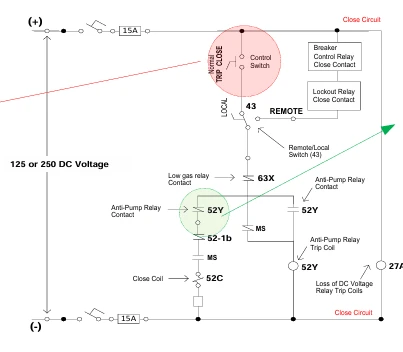
Anti Pumping Relay Circuit Diagram Explained
Here’s how the basic circuit works:
Close Circuit Components:
- Close push button or TNC switch
- Anti pumping relay (Y-relay) contact (normally closed)
- 52b auxiliary contact (CB open position)
- Closing coil (CC)
- DC control power supply
The Logic:
Close Command → Y-Relay Energizes → Y-Relay Seals In →
Y-Relay Opens NC Contact in Close Circuit →
Close Circuit Isolated → No Further Closing Possible
When you give a continuous close command by keeping the TNC switch in close position, the picks up and the closing circuit becomes electrically isolated. Even if you now give a trip command through the emergency push button, the CB will trip but won’t close again because the close circuit is still isolated by the Y-relay.
Anti Pumping Relay Function Verification Test
As a technician, you need to test this function regularly. Here’s the standard test procedure:
Testing Procedure
Equipment Required:
- Multimeter
- Test switches
- Control power supply
- Safety equipment
Test Steps:
- Initial Setup
- Ensure circuit breaker is in open position
- Verify control power is available
- Rack out or isolate CB if required per safety procedures
- Apply Continuous Close Signal
- Keep the close button pressed continuously
- OR maintain TNC switch in close position
- Observe that CB closes ONCE only
- Verify Anti Pump Function
- While maintaining close signal, observe:
- it should be energized (check indicator or test with multimeter)
- CB should remain closed
- Close circuit should have an open contact (Y-relay NC contact opens)
- Apply Trip Command
- While close signal is still maintained, give trip command
- CB should trip open
- CB should NOT attempt to close again
- This proves anti pumping is working correctly
- Reset Test
- Remove the close signal
- Anti pumping relay should de-energize
- System should be ready for next operation
- Repeat Test
- Give another close command (momentary this time)
- CB should close normally
- Remove close signal
- Give trip command
- CB should trip normally
Expected Results:
1.Only ONE close operation per close command
2.CB does not close repeatedly even with continuous close signal
3.CB can be tripped even with close signal present
4.CB does not re-close after trip until close signal is removed and reapplied
Test Failure Indicators:
1.CB closes multiple times with single close command
2.CB attempts to close immediately after being tripped
3.Anti pumping relay does not energize
4.Y-relay does not seal in properly
According to IEEE standards for substation control circuits, this test should be performed during commissioning and periodically during maintenance.
Common Anti Pumping Relay Problems and Troubleshooting
Problem 1: Circuit Breaker Keeps Closing Repeatedly
Symptoms:
- CB closes, trips, closes again rapidly
- Pumping action observed
- Mechanical damage to CB mechanism
Possible Causes:
- Anti pumping relay failure
- Y-relay coil burned out
- Y-relay contact stuck closed
- Wiring issue in anti pump circuit
Troubleshooting Steps:
- Check if Y-relay is energizing when close command is given
- Test Y-relay coil resistance (should match manufacturer specs)
- Check Y-relay contacts with multimeter
- Verify wiring connections
- Check for loose terminals
- Inspect for signs of overheating
Solution:
- Replace faulty Y-relay
- Repair or replace damaged wiring
- Clean and check all connections
- Test circuit after repair
Problem 2: Anti Pumping Relay Not Working
Symptoms:
- CB can close repeatedly with continuous close signal
- Y-relay does not energize
- No anti pump protection
Possible Causes:
- No control power to Y-relay(Anti-pumping relay)
- Y-relay coil open circuit
- Broken wire in control circuit
- Faulty auxiliary contacts (52a, 52b)
- DC fuse blown
Troubleshooting Steps:
- Check DC control power supply voltage
- Check fuses in control circuit
- Measure voltage at Y-relay coil terminals during close operation
- Test Y-relay coil continuity
- Check 52a and 52b contact operation
- Verify wiring as per control circuit diagram
Solution:
- Replace blown fuses
- Replace faulty relay
- Repair wiring breaks
- Adjust or replace faulty auxiliary contacts
Problem 3: Circuit Breaker Won’t Close at All
Symptoms:
- Close command given but CB doesn’t close
- Y-relay energized but CB doesn’t respond
- Close coil not getting power
Possible Causes:
- Y-relay contact stuck open in close circuit
- Y-relay not resetting after previous operation
- Close signal still present from previous operation
- Mechanical issue with relay
Troubleshooting Steps:
- Remove all close signals and check if Y-relay resets
- Manually operate Y-relay and check contact operation
- Check for stuck contacts
- Verify reset circuit is functioning
- Check if any interlock is preventing close operation
Solution:
- Manually reset the anti pumping relay
- Clean relay contacts if dirty or corroded
- Replace relay if mechanically stuck
- Check and clear any active interlocks
Problem 4: Anti Pumping Relay Failure During Testing
Symptoms:
- Relay fails verification test
- Inconsistent operation
- Sometimes works, sometimes doesn’t
Possible Causes:
- Weak relay coil
- Poor contact pressure
- Loose connections
- Aging relay components
- Improper settings in numerical relays
Solution:
- Check all connections tightness
- Test relay pickup and dropout voltages
- Replace aging relays
- For numerical relays, verify anti pump logic settings
- Update relay firmware if available
Anti Pumping Relay in Modern Numerical Relays
In older substations, anti pumping was a separate electromechanical relay (Y-relay). In modern substations with numerical or microprocessor-based relays, the anti pumping function is built into the relay logic.
Advantages of Numerical Anti Pumping:
- No mechanical wear
- Programmable time delays
- Better coordination with other protection functions
- Self-diagnostics
- Remote monitoring capability
- Event recording for troubleshooting
Common Manufacturers:
- SEL (Schweitzer Engineering Laboratories) – Models like SEL-351, SEL-487
- ABB – REF615, RET615 series
- Siemens – 7SJ, 7SA series
- GE Multilin – SR750, SR760 series
- Schneider Electric – MiCOM series
When working with numerical relays, check the relay manual for specific anti pump settings and logic configuration.
Best Practices for Anti Pumping Relay Maintenance
Regular Maintenance Tasks:
Monthly Checks:
- Visual inspection for damage
- Check indicator lights (if available)
- Verify no alarms related to control circuits
Quarterly Checks:
- Test anti pump function as per procedure above
- Check all connections for tightness
- Inspect for signs of overheating
- Clean relay panel and contacts
Annual Checks:
- Complete functional testing
- Measure contact resistance
- Verify pickup and dropout voltages
- Check auxiliary contact operation
- Review event logs (for numerical relays)
- Update documentation
During Circuit Breaker Maintenance:
- Always test anti pump function
- Verify proper coordination with CB mechanism
- Check mechanical and electrical operation
- Document test results
Safety Precautions:
⚠️ Always follow these safety rules:
- De-energize control circuits before working
- Use proper personal protective equipment (PPE)
- Follow lockout/tagout procedures
- Verify voltage absence with meter
- Work with another technician (two-person rule)
- Have one-line diagram and control schematics available
- Understand the complete control circuit before testing
Frequently Asked Questions (FAQ)
The anti pumping relay prevents a circuit breaker from closing repeatedly when a continuous close command is present. It allows only one close operation per close command, protecting the CB mechanism from damage caused by rapid open-close cycles (pumping).
When a close command is given, the anti pumping relay energizes and seals itself in. It then opens a contact in the close circuit, electrically isolating the closing coil. This prevents any further closing operations until the close command is removed and the relay resets.
Without anti pumping protection, concurrent close and trip commands can cause the circuit breaker to pump (repeatedly open and close). This causes severe mechanical damage, creates dangerous arc conditions, and reduces equipment life.
Follow this procedure:
1.Give continuous close command to CB
2.CB should close once only
3.While maintaining close signal, give trip command
4.CB should trip but NOT close again
5.Remove close signal
6.Anti pumping relay should reset
7.System ready for next operation
Never bypass anti pumping relay during normal operation! It can only be temporarily bypassed during specific maintenance or testing procedures, and only by qualified personnel following proper safety procedures. Always restore normal operation after testing.
Last words
This relay is a simple but critical component in circuit breaker control circuits. As a technician, understanding how it works, how to test it, and how to troubleshoot problems will help you maintain reliable substation operations.
For more information on circuit breaker protection and control circuits, visit our comprehensive substation guides or check out these related topics:
Related Articles:
- Protection Relay Basics
- Trip Circuit Supervision
- Circuit Breaker Auxiliary Contacts
- Substation Control Circuits
External Resources: