

What Is a Grid Station?
A grid station, also called an electrical substation or grid supply point (GSP) , links power plants to the communities they serve. It receives bulk high-voltage power (typically 500kV, 220kV, or 132kV) from generating stations or neighboring grid stations and relays it onward across long distances toward regional networks.
Since electricity is generated at voltages too high for direct use by homes or industry, grid stations bridge that gap: they receive incoming power, step voltage up or down via transformers, and route it to distribution substations or end users. At 220 kV and above, this relies on precision equipment CTs , CVTs, digital relays, marshalling kiosks, and automated circuit breakers — that detect and clear faults within milliseconds to keep the network stable.
Beyond routing power, grid station keep the grid reliable by connecting generation to distribution and maintaining a steady, controlled electricity flow. They also help the system absorb demand fluctuations and integrate renewable energy sources. In short, grid stations are the operational backbone of the power grid, moving electricity safely and efficiently from generation to end use.
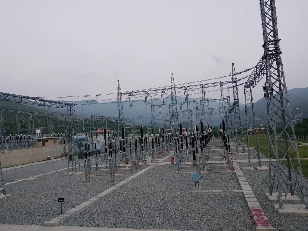
2. Core Purpose and Main Functions of grid station
primary functions of a grid station
- Voltage Transformation: High transmission voltages lower primary current flow, minimizing I^2R power losses across long distances. Power transformers step high transmission voltages down to workable distribution levels.
- Power Distribution: Bulk electricity splits into independent feeder lines that direct power to regional substations and heavy industrial loads.
- System Protection & Control: Automated protective devices monitor current and voltage in real time. When faults occur, protection relays issue immediate trip commands to circuit breakers to isolate damaged sections.
3. Key Equipment in a Grid Station Switchyard
Incoming transmission lines enter the outdoor switchyard and pass through a structured sequence of primary switchgear:
- Surge / Lightning Arrester: Diverts transient overvoltages from lightning strikes or switching surges safely to ground.
- CVT / CCVT: Steps transmission voltages down to standard secondary signals (110V AC) for relays, meters, and sync-check circuits.
- Line Trap (Wave Trap): Blocks high-frequency Power Line Carrier (PLC) teleprotection signals from entering the station busbar, confining carrier signals to the transmission line.
- Line Isolator & Earth Switch: Provides a visible physical break to isolate de-energized lines and grounds them before maintenance work.
- Circuit Breaker: Automatically interrupts load currents and heavy short-circuit fault currents using an arc-quenching medium (SF_6 gas).
- Power / Auto-Transformer: Converts incoming transmission voltages to lower system voltages through electromagnetic induction.
- Busbar: High-capacity metallic conductor that collects incoming power and distributes it across multiple bay circuits.
- Marshalling Kiosk (MK): The central junction interface in the switchyard (e.g., panel designation =D012+S2) that aggregates multi-core control, auxiliary contact, and secondary CT/VT wiring before routing them indoor to the relay panels.
4. The One-and-a-Half Breaker Scheme
High-voltage grid stations operating at 220kV and above utilize resilient busbar layouts, such as the One-and-a-Half Breaker Scheme, to ensure continuous power delivery during maintenance or fault conditions.
Operational Advantages
- Breaker Count: Two outgoing circuits share three circuit breakers (3/2 = 1.5 breakers per feeder circuit).
- Zero-Outage Maintenance: Any circuit breaker can be isolated for testing or maintenance without interrupting power to either connected feeder line.
- High Redundancy: If a busbar fault occurs on Busbar 1, power continues to flow through the center (Mid-CB) breaker to Busbar 2.
5. Instrument Transformers: CTs and CVTs
Relays and digital instruments operate on secondary signal levels. Instrument transformers scale high primary currents and voltages down to standard control levels.
Voltage Measurement (CVT)
The line or busbar CVT scales primary system voltages down to standard secondary outputs, typically:
220 kV under root 3 slash 110V under root 3
Secondary wires pass through miniature circuit breakers (MCBs) inside local junction boxes to feed distance protection, over-flux relays, sync-check units, and event recorders in parallel.
Current Measurement (CT)
Multi-core Current Transformers (CTs) feature specialized internal secondary cores matched to specific protection or metering functions:
- Core 1 (Metering): High-precision core dedicated to tariff metering and energy accounting.
- Core 2 (Main Protection / REF): Feeds secondary current to main protection relays, such as Restricted Earth Fault (REF) schemes.
- Core 3 (Backup / O/C & E/F): Supplies secondary current to directional overcurrent, earth fault, and breaker failure logic.
- Core 4 (Differential Protection): Uses specific transformations (e.g., 2400-1200/1A) for busbar or transformer differential protection relays.
Safety Rule: Never open-circuit an active CT secondary winding. Unused CT terminals must be shorted together on dedicated shorting terminal blocks (e.g., Cabur SCB.6). Open secondaries produce dangerous inductive voltage spikes that destroy insulation and create severe flashover hazards.
6. Substation Protection Architecture & Relay Zones
Grid station safety depends on overlapping, multi-layered protection zones. If a fault occurs, the corresponding relay zone isolates only the affected equipment while keeping the rest of the network energized.
Primary Protection Functions and Operating Boundaries
| Protection Scheme | Relay Device Type | Input Sources | Protective Zone Boundary & Function |
| Distance Protection (Main 1) | Siemens SIPROTEC (e.g., 7SA612) / SEL | CT Core 2 & Line CVT | Zone: Transmission line. Calculates impedance (Z = V/I) to trip instantaneously for internal line faults within 20 milliseconds. |
| Transformer Differential (87T) | Siemens SIPROTEC 7UT613 | Multi-side CT Cores (HV & LV CTs) | Zone: Bounded strictly between the primary HV and LV CT locations. Compares current-in vs. current-out with bias/restraint. |
| Restricted Earth Fault (REF) | Siemens SIPROTEC 7SJ804 | Phase CTs + Neutral Bushing CT | Zone: Single winding span (HV or LV). Provides high-sensitivity detection for winding-to-ground faults near neutral points using stabilizing resistors/Metrosil units. |
| Overcurrent & Earth Fault (O/C & E/F) | Siemens SIPROTEC 7SJ802 | CT Core 3 (HV or LV side) | Zone: Non-unit backup protection. Time-graded to clear sustained overloads or ground faults if primary protection fails. |
| Over-Fluxing Protection (V/Hz) | Siemens SIPROTEC 7RW802 / 7RW60x | Voltage Transformer (-T26, 220kV Bus) | Zone: Transformer core. Monitors voltage-to-frequency ratio (V/f) to prevent core overheating from over-excitation. |
| Mechanical Protection | Interposing Relays (7PA27) | Mechanical switches (Buchholz, WTI, OTI) | Zone: Transformer main tank and OLTC enclosure. Detects gas accumulation, rapid oil pressure rise, and excessive winding/oil temperatures. |
7. Control & Breaker Operation: Tripping and Closing Logic
Dual-Redundant DC Tripping Distribution
To prevent a single electrical failure from disabling station protection, control systems run on dedicated 220V DC battery supplies divided into independent feeds:
protection relay commonds
- Trip Circuit I (DC Feed 1): Dedicated to Primary Protection relays (e.g., Main 1 Distance, Differential) and Trip Coil 1 (-YT1).
- Trip Circuit II (DC Feed 2): Dedicated to Secondary/Backup Protection relays (e.g., Main 2 Distance, REF, O/C) and Trip Coil 2 (-YT2).
- Breaker Failure Protection (50BF): If a breaker receives a trip command but fails to open within a set time delay, 50BF logic fires trip signals to all adjacent breakers to isolate the fault.
- Trip Circuit Supervision (TCS): Continuously monitors the electrical continuity of trip coils -YT1 and -YT2 in both open and closed breaker states, raising an alarm if control wiring breaks.
Breaker Closing Interlocks
Closing a 220kV circuit breaker requires verifying multiple interlocking conditions through control logic:
- Operator Close Command
2.Check Line / Bus Isolator Positions (-Q11, -Q12, -Q10)
3.Confirm No Active Lockout Relays (-86 Master Trip Normal)
4.Check Synchronizing Relay (-K02: Voltage, Frequency, Phase Match)
5.Energize Breaker Close Coil (-YT3 / KL1) ] ──► Breaker Closes
8. Safety Interlocking Systems
Isolators (disconnectors) cannot interrupt load or fault currents. Mechanical and electrical interlocks prevent illegal switching operations:
- No-Load Operation Interlock: Disconnector switches (-Q21, -Q22, -Q20) cannot open or close unless the associated circuit breaker is completely OPEN.
- Earthing Switch Interlock: Line earth switches (-E10) cannot close while the associated line isolator is closed.
- Dead-Line / Undervoltage Check: Closing an earth switch requires voltage confirmation from the CVT ($U <$) to prevent grounding an active, energized transmission line.
9. Electrical Clearances in AIS (Air-Insulated Substations)
Beyond the internal protection and control circuits described above, every AIS (Air-Insulated Substation) grid station must maintain minimum air clearances between live conductors, equipment, and earthed structures. These clearances prevent flashover, protect personnel during operation and maintenance, and are defined by international standards for each voltage class.
Key Governing Standards
- IEEE Std 1427-2020: Covers air-insulated substations from 1 kV to 800 kV, addressing operating clearances, safety distances, insulation coordination, and compact bus design.
- IEC 61936: Applies to electrical installations above 1 kV AC / 1.5 kV DC, defining phase-to-phase, phase-to-earth, equipment spacing, and personnel safety clearances.
Standards Comparison
| Standard | Scope | Clearance Focus |
| IEEE Std 1427-2020 | Air-insulated substations, 1 kV–800 kV | Operating clearances, safety distances, insulation coordination, compact bus design |
| IEC 61936 | Electrical installations >1 kV AC / 1.5 kV DC | Phase-to-phase, phase-to-earth, equipment spacing, personnel safety |
Clearance Definitions
- Phase-to-Phase Clearance: Minimum distance between live conductors of different phases.
- Phase-to-Earth Clearance: Minimum distance between a live part and earth/ground.
- Working Clearance: Safe distance maintained for personnel during operation and maintenance.
- Equipment Clearance: Spacing between live parts and equipment, such as structures and enclosures.
- Ground Clearance: Minimum distance of live parts above ground level.
Typical Clearance Requirements (IEC 61936 Reference)
Values below are indicative. Actual clearances must follow utility/project specifications and a formal insulation coordination study.
| Voltage Level (kV) | Phase-to-Phase (m) | Phase-to-Earth (m) | Working Clearance (m) | Equipment Clearance (m) |
| 11 | 0.14 | 0.16 | 2.0 | 1.2 |
| 22 | 0.20 | 0.24 | 2.0 | 1.2 |
| 33 | 0.30 | 0.36 | 2.0 | 1.5 |
| 66 | 0.60 | 0.65 | 2.5 | 1.8 |
| 132 | 1.10 | 1.20 | 2.5 | 2.0 |
| 220 | 1.80 | 1.90 | 3.0 | 2.5 |
| 400 | 2.50 | 2.70 | 3.5 | 3.0 |
| 765 | 5.00 | 5.40 | 4.0 | 3.5 |
Altitude Correction
Clearances increase above 1000 m elevation because reduced air density lowers the dielectric strength of air.
| Altitude | Correction |
| ≤ 1000 m | 0% |
| 1000–2000 m | +5% |
| 2000–3000 m | +10% |
| > 3000 m | +15% |
Factors Influencing Clearances
- System voltage level
- Basic Lightning Impulse Level (BIL)
- Basic Switching Impulse Level (BSL)
- Altitude and ambient conditions
- Pollution level (industrial or coastal environments)
- Insulation coordination study
Risks of Inadequate Clearances
- Flashover / arcing between conductors
- Equipment damage due to insulation breakdown
- Personnel injury from unsafe working distances
- Regulatory non-compliance leading to project rejection
Design Engineer Checklist
- Check required clearances as per IEC 61936 / applicable national codes and project specifications
- Verify BIL and BSL of equipment
- Consider altitude and environmental conditions
- Ensure adequate working and maintenance space
- Maintain ground clearance as per standards
Practical Takeaways
- Apply IEC 61936 for regional regulatory compliance and IEEE 1427 for international projects.
- Always coordinate clearances with insulation levels and equipment withstand capability.
- Account for altitude, pollution, and environmental conditions.
- Design for safety, reliability, and long-term operational stability.
Goal: Right Clearances → Safe Operation → Reliable Power Supply.
Frequently Asked Questions (FAQs)
What is the main difference between a grid station and a substation?
“Grid station” typically refers to a high-voltage transmission-level substation (220kV, 500kV) that feeds regional bulk networks, whereas “substation” is a general term applying to any voltage transformation facility.
Why do protection and control circuits operate on 220V DC power?
Substation battery banks supply uninterrupted DC control power. This guarantees that protection relays, trip coils, and emergency control circuits operate during complete AC grid blackouts.
What is the role of the Marshalling Kiosk (MK)?
The Marshalling Kiosk serves as the intermediate connection hub in the switchyard. It collects multi-core cables from switchyard primary equipment (CTs, CVTs, auxiliary contacts) and organizes them before sending signals to the indoor relay room panels.
How does SF_6 gas work inside a circuit breaker?
Sulfur Hexafluoride ($SF_6$) gas provides high dielectric strength and arc-extinguishing properties. When breaker contacts separate under fault conditions, $SF_6$ gas quenches the electrical arc within milliseconds.
Conclusion
A grid station is far more than a set of transformers and breakers,it is a tightly coordinated system where switchyard equipment, multi-layered protection relays, redundant DC tripping circuits, and carefully engineered air clearances all work together to keep power flowing safely. Understanding how these elements interact, from CT/CVT signal paths to the phase-to-earth clearance at 220 kV, gives engineers the foundation to design, operate, and maintain substations that are both reliable and compliant with international standards.