
Control circuit troubleshooting:
Control circuit troubleshooting requires a systematic and methodical approach. When a machine fails, quick diagnosis minimizes downtime and maintains efficiency. This guide focuses on open circuit faults in control systems.
Symptom: The machine does not start when the start button is pressed.
- Fault may be mechanical or electrical.
- Electrical faults can occur in the power circuit or control circuit and may be an open circuit, short circuit, or ground fault.
Method: Start at the control transformer, which links both power and control circuits. The first three steps are the same for all faults; later steps vary. Since no single procedure fits all cases, we’ll address faults one at a time, beginning with open circuits.
Three Universal Steps of Control Circuit Troubleshooting:
- Study the schematic for a circuit overview.
- Open the control panel carefully with the power ON for voltage tests.
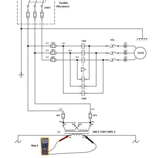
- Measure voltage at X1–X2 (transformer secondary):
- No voltage → Power circuit fault.
- Voltage present, contactor energized → Power circuit fault.
- Voltage present, contactor not energized, OL not tripped → Control circuit fault.
Open Circuit Fault:
Occurs when a wire or component is broken, stopping current flow. Troubleshooting always begins with the three universal steps before tracing the circuit step by step until voltage is lost.
Scenario A
If the motor does not start when the button is pressed, the voltage is correct at X1 and X2, the contactor is not energized, and the OL is not tripped, the fault lies in the control circuit. In Scenario A, it’s an open circuit fault inside the panel.
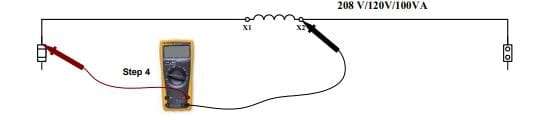
Step 4. You should check the voltage on X1 at the top of the control circuit fuse and the X2 terminal at the secondary of the control transformer. • If the correct voltage is present, continue to Step 5. • If the correct voltage is not present, then the X1 wire is open from the top of the fuse to the terminal on the secondary of the transformer.
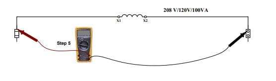
Step 5. You should check the voltage on X1 at the top of the control circuit fuse and X2 at the top of the neutral link. • If the correct voltage is present, continue to Step 6. • If the correct voltage is not present, then the X2 wire is open from the top of the neutral link to the terminal on the secondary of the transformer.
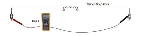
Step 6. You should check the voltage on wire #1 at the bottom of the control fuse and X2 at the top of the neutral link. • If the correct voltage is present, continue to Step 7.If the correct voltage is not present, then the control fuse is open. If the fuse is open, then there is either a short circuit or a ground fault. If the fuse is not open, then there is an open circuit fault. This is our first indication that the fault is an open circuit fault.
Step 7. You should check the voltage on wire #1 at the bottom of the control fuse and wire #2 on the bottom of the neutral link. • If the correct voltage is present, continue to Step 8. • If the correct voltage is not present, then the neutral link is open.
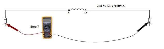
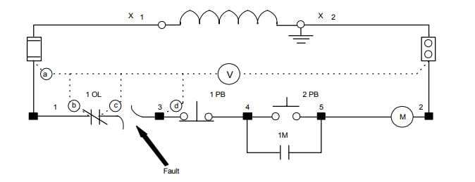
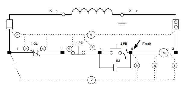
Use the schematic diagram below as an illustration for Scenario A for control circuit troubleshooting, assuming that we don’t know the location of the fault:
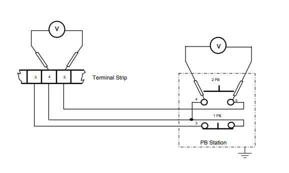
Step 16. Check the voltage at the bottom of terminal #4 and the top of terminal #5. • If the correct voltage is present, continue to Step 17. • If the correct voltage is not present, then terminal #4 is open.
Step 17. Check the voltage at the bottom of terminal #4 and the bottom of terminal #5. • If the correct voltage is present, continue to Step 18. • If the correct voltage is not present, then terminal #5 is open.
Step 18. Since you have made all the measurements possible inside the panel, the fault must be outside the panel, and you must go to the pushbutton station for 2PB. Carefully remove the cover. Check the voltage across the terminals where wire #4 and wire #5 are connected. •If the correct voltage is present, then push the 2PB pushbutton. The motor does not start. The normally open contacts for pushbutton 2PB are bad and will not close. This is the fault. • If the correct voltage had not been present, then there would be an open circuit between the bottom of the #4 terminal and the bottom of terminal #5 outside the panel.
Scenario D for the
Control Circuit Troubleshooting:
The motor does not start when the start button is pressed. If the correct voltage is present at X1 and X2, the contactor is not energized, and the OL is not tripped, then the problem is in the control circuit. For Scenario D, the fault is an open circuit fault and outside the panel. Wire #5 is open between the bottom of the #5 terminal and the terminal on 2PB. Since the correct voltage is present, we must troubleshoot the system in a logical order until we lose the correct voltage. Follow steps 1 through 17 just as we did in Scenario C. The correct voltage is present from the bottom of terminal #4 to the bottom of terminal #5.
If the voltage changes from a good reading on one device to a different reading on the next device in logical order, then the device or wire in between those readings is open.
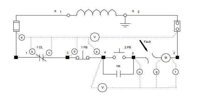
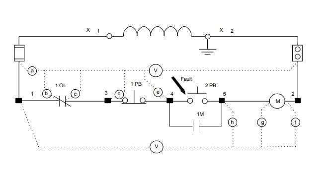
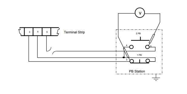
Use the schematic diagram on the following page as an illustration for Scenario D, assuming that we don’t know the location of the fault:
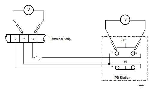
Step 18. Since you have made all the measurements possible inside the panel, the fault must be outside the panel, and you must go to the pushbutton station for 2PB. Carefully remove the cover. Check the voltage across the terminals where wire #4 and wire #5 are connected. • If the correct voltage is present, then push the 2PB pushbutton. The motor does not start. The normally open contacts for pushbutton 2PB are bad and will not close. • If the correct voltage is not present, then there is an open circuit between the bottom of terminal #4 and the bottom of terminal #5 outside the panel, so continue to Step 19.
Step 19. You know that wire #4 or wire #5 is open between the bottom of the terminal strip and the pushbutton. There are two different methods to eliminate the possibilities. First method: check the voltage across the terminal with wire #4 to the ground terminal as a reference. • If the voltage is present, then wire #4 is good, and wire #5 must be open between the bottom of the terminal strip and the 2PB. • If the voltage is not present, then wire #4 must be open between the bottom of the terminal strip and the 2PB.
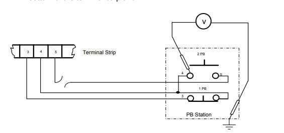
Second method: check the voltage across the terminal with wire #5 to wire #3 as a reference.
-
- If the voltage is present, then wire #5 is good and wire #4 must be
open.
- If the voltage is present, then wire #5 is good and wire #4 must be
-
- If the voltage is not present, then wire #5 must be open.
For effective control circuit troubleshooting:
-
- Start with the schematic—understand the circuit before testing.
-
- Follow a logical sequence—move systematically from the transformer outward.
-
- Document findings—Record voltages at each test point.
-
- Golden Rule: The fault is between the last working point and the first failed point.
Safety Considerations
-
- Use calibrated test equipment rated for the voltage level.
-
- Wear appropriate PPE (insulated gloves, face shields).
-
- Follow lockout/tagout procedures during repairs.
Conclusion
Mastering control circuit troubleshooting requires technical knowledge and a structured approach. By following this guide—starting at the control transformer, methodically testing, and using visual references—you can efficiently diagnose and resolve faults, ensuring minimal downtime and safe operation.