A Complete Guide to Building Power Infrastructure
Electrical Substation Construction-Electrical substations are critical components of the power distribution network, serving to transform voltage levels and facilitate the transmission of electricity.
If you’re an electrical substation contractor, project manager, or engineer working on substation construction work, this guide walks you through every phase of building these critical facilities—from the first shovel in the ground to final testing.
What Goes Into Building a Substation?
Electrical substation construction isn’t just about installing equipment. It’s a carefully complicated process that includes site selection, detailed electrical substation planning, civil construction, equipment installation, and extensive testing. Modern high voltage substation construction projects can take 18-36 months and involve dozens of specialists.
The key to success? Planning everything down to the smallest detail before work begins, then executing each phase in the right sequence. Let’s break down how professional electrical substation construction companies approach these complex projects.
Phase 1: Planning and Design – Getting It Right from the Start
Before any electrical substation installation begins, you need rock-solid planning. This isn’t the place to wing it. Every detail matters because mistakes discovered during construction are expensive and time-consuming to fix.
Creating Your Electrical Substation Drawings
The design electrical substation phase produces the blueprints for your entire project. Your electrical substation drawings package should include:
- Single-line diagrams showing how power flows through the station
- Site layout plans positioning every piece of equipment
- Protection schemes that keep the system safe from faults
- Substation control room layout plans for operator spaces
- Substation control panel wiring diagrams for every circuit
A good set of drawings anticipates construction challenges. For example, they’ll show exactly where cable sleeves need to be cast into concrete, or how cable trays will route through the control building.
What Makes Good Substation Planning?
Professional electrical substation planning addresses these critical areas:
Site Selection: You need solid ground that can support heavy transformers, good drainage, room for future expansion, and access for large equipment deliveries. Environmental factors matter too—coastal sites need extra corrosion protection, while desert locations require enhanced dust protection.
Load Analysis: How much power will this substation handle today? In 10 years? In 25 years? Your design needs to accommodate growth without requiring a complete rebuild.
Equipment Choices: Will you use Gas Insulated Switchgear (GIS) or Air Insulated Switchgear (AIS)? GIS costs more but takes up much less space—crucial for urban electricity substation points.
Standards Compliance: You’ll need to meet standards like IEEE, IEC, and local requirements. In Saudi Arabia, for example, all electrical substation construction must comply with SEC (Saudi Electricity Company) specifications.
Getting these decisions right early saves headaches later. I’ve seen projects delayed by months because someone didn’t verify that a 300-ton transformer could actually reach the site on existing roads.
Phase 2: Civil Works – Building the Foundation
Now we get to actual construction. The civil works phase creates all the structures that support and protect electrical equipment. This is where substation construction work moves from paper to reality.
Laying the Groundwork
Think of civil works as building a specialized industrial facility. You’re creating multiple structures, all of which need to integrate seamlessly with electrical systems:
Transformer Foundations: These aren’t ordinary concrete pads. Transformer foundations must handle 50-200 tons of equipment weight, resist oil in case of leaks, and often include cooling systems or fire protection. The concrete mix, rebar design, and curing process all follow strict specifications.
Control Building: This weather-protected structure houses all the brains of your substation. It needs HVAC to keep electronics cool, fire suppression systems, and physical security. The substation control room layout must be ergonomic for operators who might spend hours monitoring systems.
Cable Infrastructure: Before you can install a single cable, you need pathways. This means digging cable trenches, building underground tunnels, and installing cable trays. Every path must be shown on your electrical substation drawings.
Earthing System: Safety depends on a comprehensive grounding grid. Copper or copper-clad conductors are buried in a mesh pattern throughout the site, all interconnected and driven deep into the earth. This grid must be installed before foundations are poured.
The Critical Integration Step
Experienced electrical substation contractors stand out because they plan and build the electrical systems at the same time as the physical (civil) construction, rather than waiting until the building is already finished.
While concrete is being poured, teams install:
- Sleeves for cable penetrations through walls and floors
- Anchor bolts for equipment mounting
- Earthing connection points embedded in foundations
- Conduits for control wiring
Miss a sleeve during concrete pour? You’ll be drilling through reinforced concrete later—expensive and risky for structural integrity.
Once the basic structure is complete, early electrical work begins: installing cable tray systems, running preliminary earthing connections, and setting up temporary lighting so crews can work safely.
Phase 3: GIS Installation – The Heart of Modern Substations
After the civil works are done, it’s time for the star of the show: Gas Insulated Switchgear (GIS) installation. This is what makes modern high voltage substation construction so compact and reliable compared to older air-insulated designs.
What Makes GIS Special?
GIS uses sulfur hexafluoride (SF6) gas to insulate high voltage components. This allows everything to be packaged in sealed metal enclosures instead of requiring large air gaps. The result? A 132kV GIS substation might need only 25% of the space required by conventional equipment.
But there’s a catch: GIS is precision equipment. Each section arrives factory-tested and sealed. Your job is to assemble these modules correctly and maintain gas integrity throughout.
The Installation Process
High voltage substation installation of GIS equipment follows a strict sequence, typically supervised by manufacturer representatives from companies like ABB, Siemens, or Hyundai:
Step 1 – Equipment Positioning: Using forklifts and overhead cranes, position each GIS bay on its foundation. Precision matters—alignments are measured in millimeters.
Step 2 – Bay Assembly: Connect GIS modules together. This involves bolting flanges, verifying gas-tight seals, and filling compartments with SF6 to specified pressure.
Step 3 – LCC Panel Installation: Local Control Cubicles (LCCs) are the interface between the GIS and the control room. Mount these panels near their associated bays and connect them mechanically and electrically.
Step 4 – Auxiliary Equipment: Install and connect:
- Current Transformers (CTs) for measuring current
- Voltage Transformers (VTs) for measuring voltage
- Disconnector Switches (DS) for isolating equipment
- Earthing Switches (ES) for grounding during maintenance
- Circuit Breakers (CBs) for interrupting fault currents
Step 5 – Bus Bar Connections: Complete the high voltage connections between equipment bays. This requires specialized tooling and strict safety procedures.
The DC Power Priority
Here’s a pro tip from experienced electrical substation construction companies: establish temporary DC power to LCC panels as early as possible.
Why? Because DC power runs all your protection systems. Once you have DC power, you can start energizing control circuits, testing interlocks, and verifying protection schemes—even before the substation is connected to the main power grid.
Phase 4: Control Room – Mission Control for Your Substation
The substation control room layout is where human operators interact with the automated systems. Get this wrong, and your operators will struggle. Get it right, and they can manage complex situations efficiently.
Designing the Control Room Space
A well-designed control room balances functionality with ergonomics:
Equipment Layout: Protection and control panels line the walls, typically arranged to mirror the single-line diagram. This intuitive layout helps operators quickly understand system status.
Operator Workspace: Desks or consoles face the panel wall, equipped with SCADA monitors, alarm annunciators, and communication equipment. Operators should be able to see critical indicators without standing up.
Environmental Control: Electronics need stable temperatures, typically 20-25°C (68-77°F). HVAC systems run 24/7, with backup cooling in case of failure.
Access and Safety: The control room needs secure access control but also emergency exits. Fire suppression systems (often clean agent, not water) protect equipment.
The Earthing Foundation
Before any panels are installed, establish proper earthing. Run copper tape or bars throughout the control room floor (often beneath raised flooring). Every panel frame, every cabinet, every piece of equipment connects to this earth grid using specified sizes of copper tape.
Why such attention to earthing? Because during a fault, thousands of amperes might flow to ground. Proper earthing ensures this current has a safe path and prevents dangerous voltage differences between equipment.
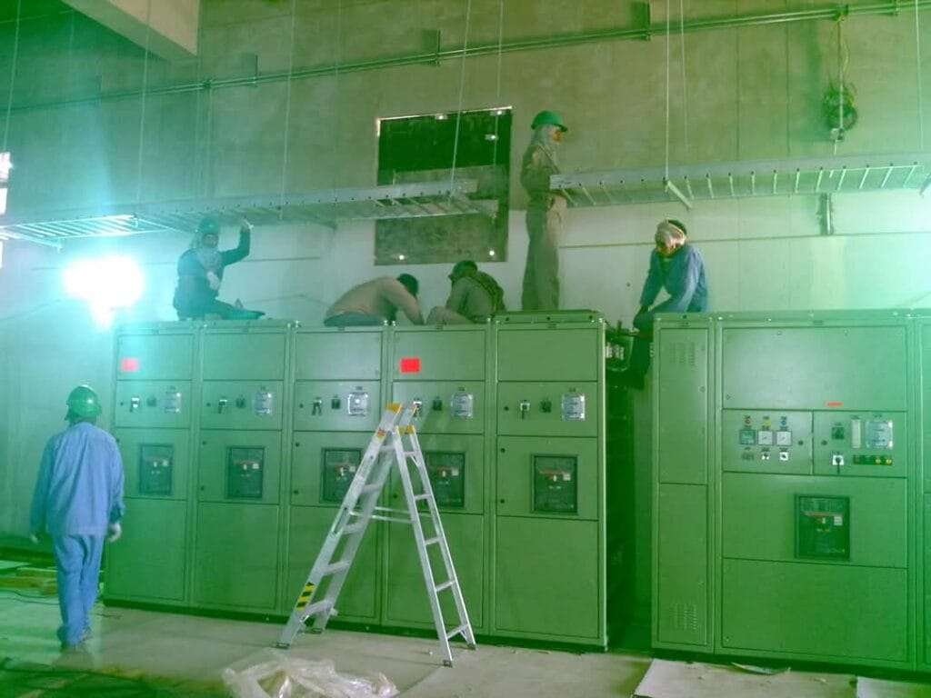
Phase 5: Cable Pulling and Connections – The Nervous System
Now comes one of the most labor-intensive phases of substation construction work: pulling thousands of cables and terminating them correctly. This is where attention to detail really counts.
The Cabling Challenge
Modern substations have complex cabling requirements. Between the GIS, LCC panels, control room, and auxiliary systems, you might install:
- Power cables (AC and DC)
- Control cables for switching commands
- Protection cables linking CTs, VTs, and relays
- Communication cables for SCADA,SAS and networking
- Instrumentation cables for monitoring
Every cable must be:
- Routed correctly through designated cable trays or conduits
- Supported properly to prevent stress on terminations
- Identified clearly with ferrules or tags matching the drawings
- Terminated precisely according to the wiring schedule
Substation Control Panel Wiring Excellence
Substation control panel wiring isn’t just connecting wires—it’s creating a reliable, maintainable system. Professional electrical substation contractors follow these practices:
Cable Glanding: Each cable entering a panel gets a proper gland (or cable entry). This provides strain relief and maintains the panel’s IP (Ingress Protection) rating against dust and moisture.
Cable Dressing: Inside panels, cables are bundled neatly, routed along designated pathways, and secured with ties. Good cable dressing looks professional but more importantly, it prevents mistakes during future maintenance.
Ferrule Marking: Every wire gets a ferrule (small numbered sleeve) matching the circuit identifier on the electrical substation drawings. This makes troubleshooting much easier.
Documentation: As you terminate each cable, document it. Record actual cable numbers, terminal locations, and any deviations from drawings. This creates an as-built record invaluable for future maintenance.
Implementing Control Schemes
This phase involves wiring multiple complex systems:
- TCS (Transmission Control System): Master control for coordinating breaker operations
- Bus Bar Protection: Fast differential protection to detect faults on bus bars
- Breaker Failure (BF) Protection: Backup that operates if a breaker fails to trip
- Annunciation: Alarm systems alerting operators to abnormal conditions
- SCADA: Communication links for remote monitoring and control
- Sequence of Events (SOE): Millisecond-precise recording of what happened during disturbances
- Trip and Fault Recording (TFR): Capturing waveforms during faults for analysis
- Substation Automation System (SAS): Integrated platform controlling everything
- Communication Networks: Ethernet, fiber optics, and serial links connecting devices
Each system has dozens or hundreds of wires that must be correct. One wrong connection can cause a protection failure or false trip.
Phase 6: Testing and Commissioning – Proving It All Works
This is where the rubber meets the road. All that planning, construction, and wiring gets validated through comprehensive testing. For high voltage substation installation projects, commissioning can take 2-4 months and represents the most critical phase.
Pre-Commissioning Tests: Catching Problems Early
Start with basic verification before applying any voltage:
Visual Inspection: Walk through every panel. Check every connection. Look for loose wires, missing ferrules, incorrect routing, or any visible issues. It’s tedious but catches many problems.
Insulation Resistance Testing: Using a megohmmeter, test insulation between conductors and to ground. This reveals damaged cable insulation, moisture infiltration, or contamination. Minimum acceptable values are typically 10-100 megohms depending on voltage level.
Continuity Testing: Verify that cables connect where the drawings say they should. Ring out CT and VT secondary circuits, control circuits, and earthing connections.
Auxiliary Relay Testing: Test each protective relay, timer, and auxiliary relay individually. Inject test signals, verify pickup/dropout values, and confirm timing matches specifications.
Circuit Breaker and Protection Device Testing: Check that miniature circuit breakers (MCBs), molded case circuit breakers, and fuses have correct ratings and trip properly.
Functional Testing: Making Everything Work Together
Now test complete functions, not just individual components:
GIS Interlocks: Try to operate equipment incorrectly (with protection interlocks active). The interlocks should prevent unsafe operations like closing a disconnector under load.
Control Sequences: Command a circuit breaker to close from the control room. Verify that the command reaches the breaker, status indications update, and alarms function correctly.
Protection Schemes: Using a relay test set, simulate fault conditions. Inject currents and voltages that represent different fault types. Verify that:
- Relays detect faults correctly
- Trip signals are sent to the right breakers
- Backup protection operates if primary fails
- Fault records capture the event
SCADA and Automation: Test communication between field devices and the SCADA system. Verify that measurements update, commands execute, and alarms propagate to the master station.
According to IEEE commissioning standards, you should test both normal operations and abnormal/fault scenarios. Don’t just verify that things work—verify they fail safely.
Integration Testing: The Final Hurdle
For extensions to existing substations, integration testing connects new equipment to operating systems. This requires extreme care because errors can affect existing service:
Point-by-Point Verification: Using interfacing drawings, verify every connection between new and existing equipment. Don’t assume anything—check it all.
Open Loop Testing: Test new circuits with the substation isolated from the power system. Simulate conditions and verify responses without risk of affecting customers.
Closed Loop Testing: With coordination between site engineers and system operators, carefully integrate the new substation into the live network. Monitor closely for any unexpected behavior.
Master Station Testing: Verify that remote control and monitoring work correctly. Test communications, command execution, and alarm reporting between the substation and the utility control center.
Only after all tests pass successfully—and the utility accepts the results—can the substation be commissioned and placed into regular service.
Read about common commissioning challenges and practical solutions.
Regional Standards and Requirements
Electrical substation construction management varies significantly by region. Understanding local requirements is essential for electrical substation construction companies working internationally.
Saudi Arabia: Building for Extreme Conditions
In Saudi Arabia, electrical substation construction follows rigorous SEC (Saudi Electricity Company) standards. These account for harsh environmental conditions:
Desert Climate: Equipment must operate reliably at ambient temperatures exceeding 50°C (122°F). This requires:
- Higher-rated cooling systems for transformers
- Temperature-resistant cable insulation
- HVAC systems sized for extreme cooling loads
Dust and Sandstorms: The desert environment demands:
- Enhanced IP ratings (typically IP54 or higher)
- Air filtration systems for control rooms
- Sealed cable entries and gasket systems
Coastal Corrosion: For substations near the Red Sea or Arabian Gulf:
- Special anti-corrosion coatings on all steel structures
- Stainless steel hardware where practical
- Regular inspection and maintenance schedules
Seismic Requirements: Saudi Arabia has moderate seismic activity, requiring:
- Seismic analysis of equipment mounting
- Flexible connections for rigid components
- Foundation designs accounting for ground motion
These stringent standards ensure reliable power infrastructure throughout the Kingdom and provide a useful benchmark for quality construction anywhere.
International Standards: Speaking a Common Language
Professional electrical substation contractors working globally must navigate multiple standards frameworks:
IEC (International Electrotechnical Commission): Used throughout most of the world, IEC standards cover equipment specifications, testing procedures, and safety requirements. IEC 61850 is particularly important for substation automation.
IEEE (Institute of Electrical and Electronics Engineers): Dominant in North America, IEEE standards address everything from protection relaying to testing procedures. IEEE also publishes useful guides covering recommended practices.
ANSI (American National Standards Institute): US-specific standards that supplement IEEE requirements, particularly for equipment ratings and testing.
BS (British Standards): Still used in UK and many Commonwealth countries, gradually harmonizing with IEC standards.
Smart contractors maintain familiarity with multiple frameworks and can adapt designs and procedures as needed.
Real-World Success Factors
Having covered the technical process, here are some practical insights from successful projects:
Early Coordination: Get all stakeholders involved early—utility engineers, manufacturers, contractors, and commissioning teams. Decisions made in design affect commissioning months later.
Document Everything: Create detailed as-built drawings reflecting actual installations. Future maintenance teams will thank you. Take photos during construction showing cable routes before they’re covered.
Build in Flexibility: Include spare capacity in cable trays, extra conduits through walls, and additional panel space. Retrofitting is always more expensive than installing it right the first time.
Quality Over Speed: Rushing commissioning causes problems. Better to spend an extra week testing thoroughly than to energize with hidden defects.
Invest in Training: Ensure operators understand the new substation before commissioning. Conduct walkthroughs, explain protection schemes, and practice emergency procedures.
Conclusion: Building Power Infrastructure That Lasts
Successful electrical substation construction is a marathon, not a sprint. From initial electrical substation planning through final commissioning, projects typically span 18-36 months and require coordination among dozens of specialists.
The complexity is real. Modern substation construction work involves civil engineering, mechanical installation, complex substation control panel wiring, sophisticated protection schemes, and exhaustive testing. Every phase builds on previous work, and mistakes in early phases affect everything that follows.
But when done right, you create infrastructure that reliably serves communities for 30-50 years. That transformer foundation you engineered? It might support equipment until 2075. Those electrical substation drawings you detailed so carefully? Maintenance crews will reference them for decades.
Whether you’re planning your first high voltage substation construction project or you’re a seasoned electrical substation contractor looking to refine your approach, the key principles remain constant: plan thoroughly, execute carefully, test comprehensively, and document everything.
The power grid depends on these facilities. Every home, business, hospital, and school relies on substations to deliver reliable electricity. Building them right matters.
For more insights on substation design, construction, and maintenance, explore additional resources at SubstationFaults.com—your comprehensive guide to power system infrastructure.